
Mobile Robot Autonomous Navigation: SLAM & A*
We took an MBot (Classic) from bare hardware to closed-loop autonomous navigation. The stack includes wheel-speed feed-forward with PID, gyrodometry, occupancy-grid mapping from 2D LiDAR, Monte Carlo Localization (MCL), lightweight SLAM, A* planning, and frontier exploration—enough to build a map, localize within it, and reach goals through clutter.
Video Demo
System Overview
Three layers keep the robot honest under sensor noise and wheel slip:
(1) Control — feed-forward from wheel calibration + PID feedback; motion model uses Rotate–Translate–Rotate (RTR)
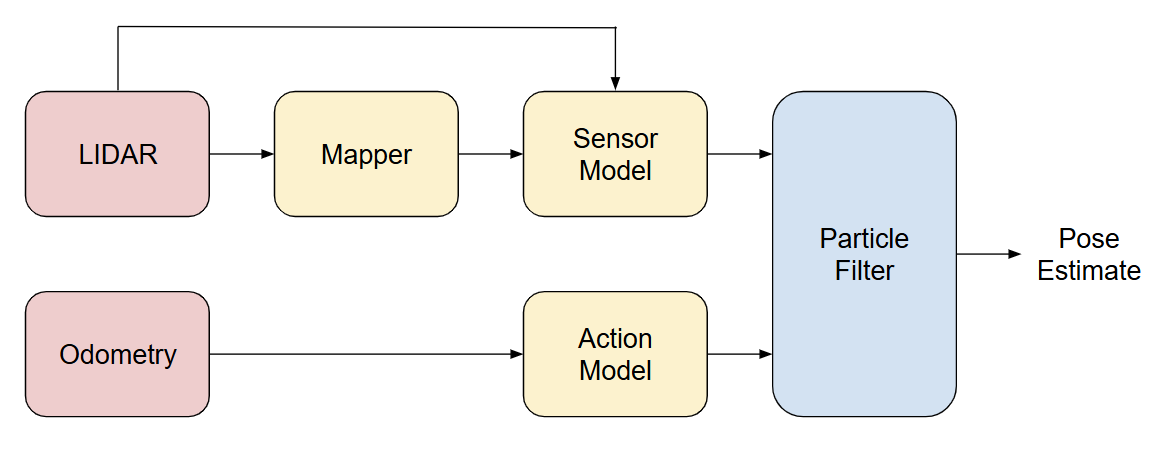
(2) Mapping & Localization — log-odds occupancy grid + particle-filter (MCL) with LiDAR likelihoods
(3) Planning — 8-connected A* on an inflated costmap, plus simple frontier exploration for unknown space
Hardware
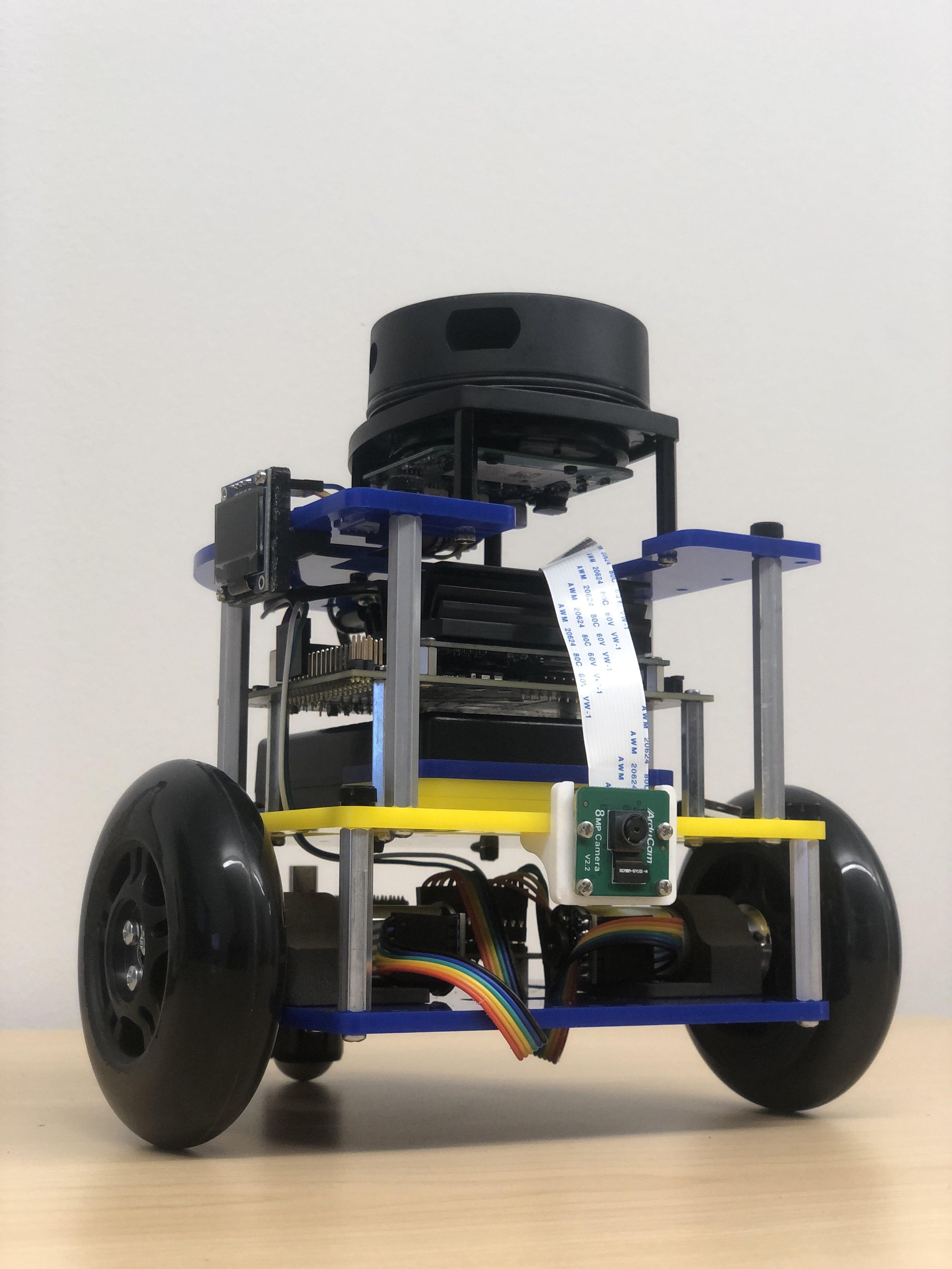
- MBot (Classic), differential drive
- Jetson Nano controller
- Wheel encoders (per-wheel)
- 2D LiDAR + 3-axis IMU
- Battery + power/regulation board
Calibration & Low-Level Control
We measured wheel speed vs PWM to derive a linear feed-forward model (PWM = m·v + b) and wrapped it with a per-wheel PID for accurate tracking. RTR motion (spin→drive→spin) reduces heading drift compared to naive differential drive. This layer exposes “go-to” primitives for the planner.
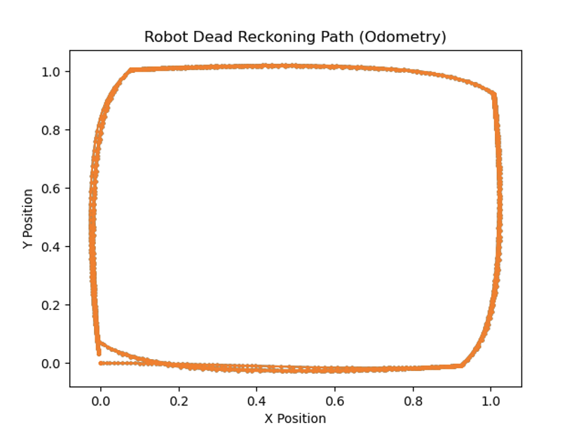
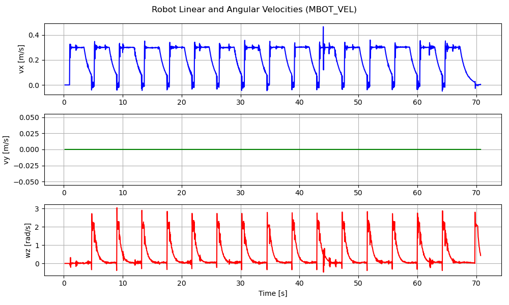
We validated odometry with a 1 m square dead-reckoning test: each edge runs RTR (rotate→translate 1 m→rotate) while logging encoder ticks, gyro yaw, and wheel speeds at 50–100 Hz. Pure encoder odom drifts in heading; fusing the gyro tightens the loop so the path closes near the start with small, repeatable error. The velocity trace shows clean ramp/cruise/ramp; tuned PID prevents bowing or spiraling, making the “go-to” primitive metrically reliable for A*/MCL.
Mapping (Occupancy Grid)
LiDAR scans are integrated into a log-odds occupancy grid using Bresenham raycasting to mark free vs occupied space. We inflate obstacles to account for the robot footprint and planning safety margins.
Localization (MCL)
A particle filter tracks pose on the grid. The RTR odometry drives the motion update; the LiDAR grid-correlation likelihood gives the measurement update. We resample by effective sample size to avoid particle deprivation.
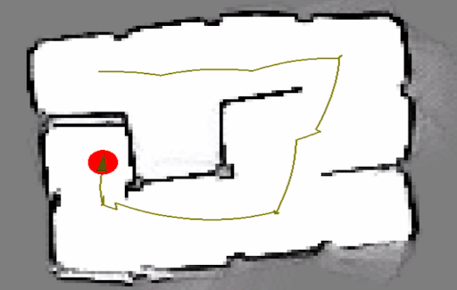
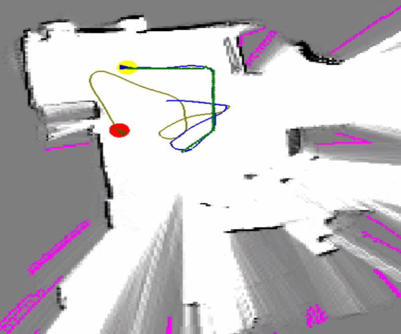
SLAM
Combining the mapper with MCL yields a lightweight RBPF-style SLAM loop: odometry proposes; the map and LiDAR likelihood correct; the grid evolves as the pose graph stabilizes. This reduces drift and tightens alignment over time.
Planning & Exploration
A* plans on an 8-connected lattice with an admissible diagonal heuristic. Unknowns carry neutral costs; inflated obstacles discourage risky shortcuts. Frontier exploration (free cells adjacent to unknown) gives a fast baseline for autonomous coverage.
Results
- Control: Stable wheel-speed tracking and clean turns with RTR.
- Mapping/SLAM: Maps align with maze geometry; localization error drops as particles converge.
- Planning: Reliable goal reaching in open and maze-like layouts, with predictable runtime.